(1) self-locking port terminal in the sheath locking device, conventional terminal self-locking port generally has three positions, the front of the terminal, the back of the terminal, both sides of the terminal face, its role is to fix the terminal in the sheath, to prevent the terminal from egress (fall out of the sheath outside).
(2) core crimping area wire conductor and the contact area of the terminal, the current and signal through this contact area between the terminal and the wire and electrical appliances for transmission. At the same time is also to ensure that the electrical and mechanical properties of the most important one area.
(3) insulation crimping area wire insulation and terminal contact area, the role of this area has 2:
① prevent the wire insulation layer back shrinkage caused by the end of the sheath with the wire core exposed, in the case of high voltage arc connection short circuit phenomenon;
② insulation crimping area in the terminal tail and wire package contact, limiting the swing between the wire and the terminal, to prevent the possibility of breaking the core due to the large swing.
(4) fixed guide rail terminals into the sheath when a guiding device, fixed guide rail has two main roles:
① when the terminal into the sheath to play a guiding role;
② after the terminal into the sheath to play a fixed terminal role, so that the terminal can not turn in the sheath or swing around to ensure that the terminal and terminal, terminal and sheath assembly and stability.
(5) strip cut-off point terminals in the cold stamping connection process, crimping die will be the location of the terminal and strip separation.
(6) before and after the protection of the mouth in the cold stamping connection process for the protection of the wire core crimping area in the wire core is not damaged, in the crimping after extrusion deformation left after the raised mouth.
(7) crimping out of the head wire and terminal after the completion of the cold stamping connection, before the protection of the wire core in front of the mouth, that is, the transition zone in the wire core.
(8) buffer transition zone for the stamping connection process between the core crimping area and insulation crimping area, the main role for the cold stamping connection caused by deformation and stress diffusion area.
2.Each functional area of the terminal
Figure 2 shows 3 types of terminals with different self-locking positions and different locations of their functional areas.
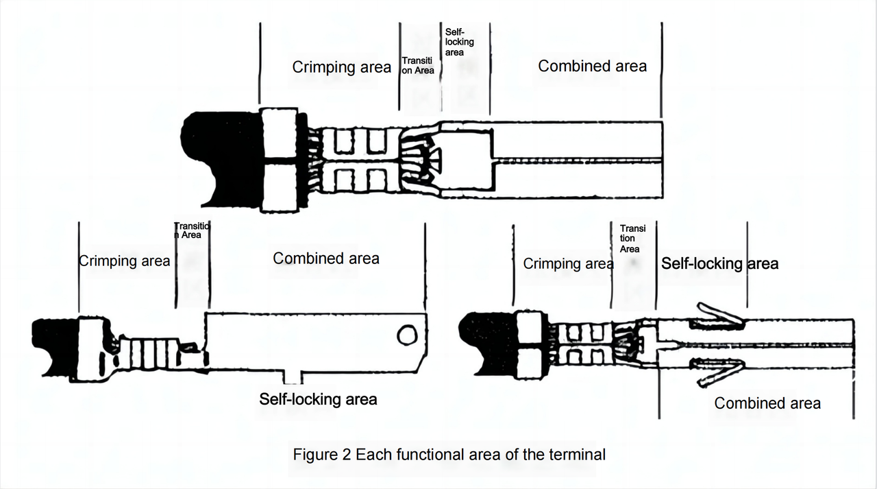
(1) crimping area terminals and wires in full contact with the region, in the actual application process for the die in the terminal extrusion deformation area, including the core crimping area and insulation crimping area.
(2) transition zone crimp zone and the combination of zone or crimp zone and self-locking zone connection transition area, the main role is to articulate, transition, crimp out the head placed.
(3) self-locking area terminal self-locking in the region, that is, the terminal and the sheath between the fixed locking area used.
(4) combined with the area of the male and female terminals for the transmission of current or signal and installed together when the full contact between the two areas.
3. The important control parameters when the terminal is connected by cold stamping
3.1. Crimp head length
The length of the terminal crimp head on the crimp connection after the terminal performance is more serious, in the actual application must meet the requirements of 2 points:
① crimp out visible, only the crimp out visible to more strongly ensure that the crimp after the terminal pull-off force, to meet the mechanical properties;
② crimp out can not be extended to the terminal bonding area and self-locking area, otherwise it will affect the terminal and the assembly performance of the sheath, so that the terminal can not be properly installed in the sheath, but also affect the ideal contact between the male and female terminals, and sometimes lead to butt sheath can not be fully assembled and locked.
Crimp head length value by the terminal itself to determine the characteristics of different specifications of the terminal on the head length of the value of different requirements, different manufacturers design of the terminal on the head length requirements are also different.
Taking into account the specifications of the terminal to determine the crimp length of the terminal, small specifications of the terminal with the crimp small specifications of the wire when the crimp head length is short, large specifications of the terminal with the crimp large specifications of the wire when the crimp head length is relatively long.
For example, some conventional terminals due to different manufacturers and users, the requirements of the crimp head length are different.
(1) MOLEX requires that the length of the crimp tip is visible twice the value of the outer diameter of the wire core, and the maximum can not be extended into the bonding area.
(2) DELPHI requires a maximum crimp length of 1mm.
(3) YAZAKI requires that the crimp out length of the terminal is 0.1~1.0mm.
(4) AMP requires the crimp out length of the terminal to be 0.5~1.0mm, and some of the more precise terminals are 0.13~0.51mm.
(5) KET requires the terminal crimp out the length of 0 ~ 2.0mm.
(6) JST requires the length of the head must be visible.
(7) Some Japanese companies will be crimped out the length of the value specified in 0.5 ~ 1.5 mm.
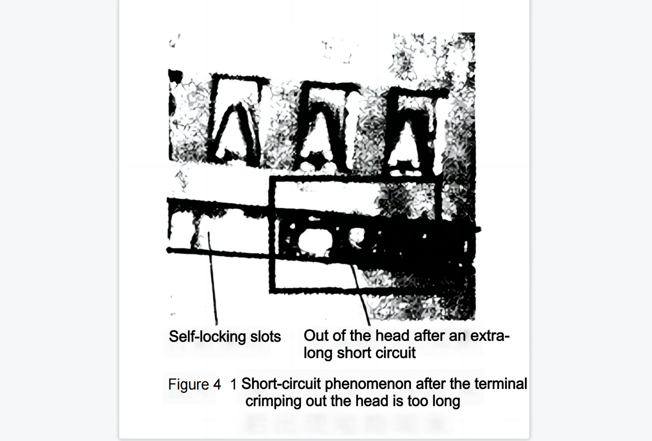
In general, the above values are only a conventional specification, for some special terminals, but also according to the application of the terminal to determine, such as the Great Wall elf and other cars in the engine ECU docking 81PIN model 368290 ~ l sheath 928999-1 terminal, crimp head must be controlled in 0 ~ 0.5 mm. when this value exceeds 0.5 When this value exceeds 0.5 mm, there may be difficulties in inserting the self-locking bar: and self-locking bar into the sheath, the adjacent hole in the core connection of the short circuit phenomenon.
As shown in Figure 4
3.2.Wire core, insulation layer visible degree
The location of the core and insulation in the buffer transition zone is one of the most important factors in the quality of a cold stamped terminal connection, and the core and insulation must be visible in this zone.
The optimal cold press connection requires that the core and insulation be exposed in the buffer transition zone for equal lengths, but in practice this is difficult to achieve, but both must be visible at the same time.
When the core is not visible in this area, the wire insulation layer is pressed into the core crimping area, resulting in crimped electrical properties reduced; when the insulation layer in this area is not visible, the wire insulation layer is not properly pressed by the terminal, the wire core lost protection, the use of the wire core may be broken phenomenon, and subsequently lead to a decline in electrical performance, a serious safety accident.
The following examples to analyze the requirements of different manufacturers and users of conventional terminal parameters. Some Japanese companies will be the core and insulation layer in the transition zone in the location of the parameters: wire stripping port and terminal insulation crimping area before the port size of 0 ~ 1mm.
MOLEX, DELPHI, YAZAKI, AMP, KET, JST requires the insulation layer and the wire core crimping area between the wire insulation layer and the wire core must be visible.
Lead Tech is a professional company who has been dealing with automotive connectors supplying for over 10 years,
who happens to be a specialist mainly help you solve your supplying urgencies.
If you are interested in more articles, feel free to click likes and reach us @www.leadtech-in.com