3.3. Cutting length of tape
When terminals are connected by cold pressing, the length of the rear end of the terminal insulation crimping area from the cut-off point of the strip, or the length of the front end of the terminal from the cut-off point of the front strip, i.e., the cut-off length of the strip. In the process of cold press connection crimping, when the terminal is cut from the tape, if the retained tail material is too long or too short, it will lead to three kinds of bad consequences:
① After the terminal is inserted into the sheath, the excessively long metal tails will extend to the rear end of the sheath, and the higher voltage will cause arcing between neighboring contacts of the connector;
② If the tail material at the front part of the terminal is too long, it will interfere with the joining of the terminal and the sheath, and the terminal and the terminal;
③ When the cut-off length of the material strip at the front and rear ends of the terminals is retained small or even invisible, there may be a problem of the terminals being cut, resulting in the terminals being unusable. As follows, different manufacturers have made different requirements for the cut-off length of the tape of conventional terminals.
(1) DELPHI stipulates that the front cut tape must be visible, and the rear end tape cut length must be visible and maximum 0.5mm.
(2) AMP 250 and 070 terminals for the rear end of the tape cut length must be visible, maximum 0.25mm.
(3) YAZAKI will be cut off at the rear end of the tape length of 0-0.3mm, the maximum not more than 0.5mm.
(4) KET specifies the front and rear material strip cut-off length to be no more than 0.5mm max.
0.5mm.
(5) MOLEX provisions of the front and rear end of the tape cut length of about 1 ~ 1.5 times the thickness of the terminal material.
In general, before and after the cut-off length of the tape must be visible, the maximum can not affect the assembly performance of the terminal, the end of the tape can not extend the end of the sheath.
3.4. Front and rear protection ports
In the process of connecting terminals and wires, the front and rear protection ports play a protective role for the wire core, and the rear protection port is particularly important. In the cold stamping connection process, if there is no protection port or protection port is too small, crimped wire core will be cut off by the terminal or cut injury, so that crimped terminals after the mechanical properties and electrical properties reduced, and even safety hazards; when the protection port is too large, it will make the terminals and wire contact area is reduced, mechanical properties can not be guaranteed at the same time as the electrical properties are also reduced, generally crimped terminals and wires after the contact area must be greater than the cross-sectional area of the wire. Generally, the contact area between the terminal and wire after crimping must be larger than the cross-sectional area of the wire. The following examples to analyze different manufacturers and users of conventional terminals to make different requirements.
(1) DELPHI on the minimum provisions, the provisions of the protection of the mouth must be visible.
(2) AMP on the 070 and 250 terminal requirements: the front protective port maximum of 0.25mm, after the protective port of 0.3 ± 0.13mm.
(3) MOLEX provisions of the front protective port visible, after the protective port is about 2 times the value of the terminal material thickness.
(4) YAZAKI stipulates that the rear protection port 0.2 to 0.8mm.
(5) KET stipulates that the front and rear protection port 0.3 to 0.8mm.
In general, the best state of the cold press connection is: before and after the protection port are visible, does not affect the mechanical and electrical properties after crimping.
3.5. Deformation of terminals
Terminals are generally deformed to varying degrees after crimping, and the deformation of the terminals may lead to undesirable consequences as follows:
①The terminal cannot fit into the sheath;
②The terminal is damaged;
③ male and female terminals docking is not in place;
④ terminal docking local contact, contact resistance is too medium, affecting the electrical conductivity, and sometimes local overheating caused by spontaneous combustion of the vehicle and other safety accidents.
Terminal deformation is generally divided into bending and twisting deformation, in practice, different manufacturers and users of this parameter requirements are different.
(1) AMP stipulates that the plug can be bent up 1 °, socket can be bent down 3 °.
(2) YAZAKI provisions on the maximum 3 ° bending, bending the maximum 1 °, twisting the maximum 1 °.
(3) KET stipulates that the maximum upward and downward bending does not exceed 30 ~ 6 °, the maximum left and right bending does not exceed 3 ~ 6 °, the maximum degree of torsion does not exceed 3 ~ 6 °.
3.6. Terminal crimp height, width and pull-off force
The height and width of the terminal cold press connection is a determined value, when the terminal design molding, terminal crimp height and crimp width has been determined, but due to the different design manufacturers design terminals with reference to different standards of conductors, the crimp height value is different.
Such as 173631-1 terminals in the use of Japanese standard 0.5mm ⊃2; wire and the use of American standard AWG20 wire crimp height values are different, so in the actual application of crimp height also needs to be determined according to the actual use of wire specifications.
Terminal crimp width and height in the terminal cold press connection process is a very important parameter, when the crimp height is too high, the terminal core crimp area in the wire deformation is not in place, the terminal and wire contact resistance is high, low electrical properties, terminal crimping mechanical strength is not enough to ensure that the pull-off force. When the terminal crimping height is too low, the wire deformation in the core crimping area is serious, resulting in a substantial reduction in the cross-sectional area of the wire in the crimping area after crimping, the current-carrying capacity of the wire is weakened, and the terminal and wire contact resistance increases, and the electrical properties are reduced.
At the same time, due to the large compression ratio leads to a reduction in the cross-section of the wire after the terminal crimp connection mechanical strength is not enough, the pull-off force is reduced, and when there is a serious phenomenon of the wire core is cut off. Crimping on the mechanical properties and electrical properties of the impact shown in Figure 5.
In practice, the most practical way to control the terminal crimping performance is to use the pull-off force to test its mechanical strength, because the pull-off force standard test value is through the profile experiment, electrical properties, mechanical strength and other tests, a comprehensive measure of a simple and effective control method. As can be seen in Figure 5, the curvature of the mechanical strength curve has the greatest change.
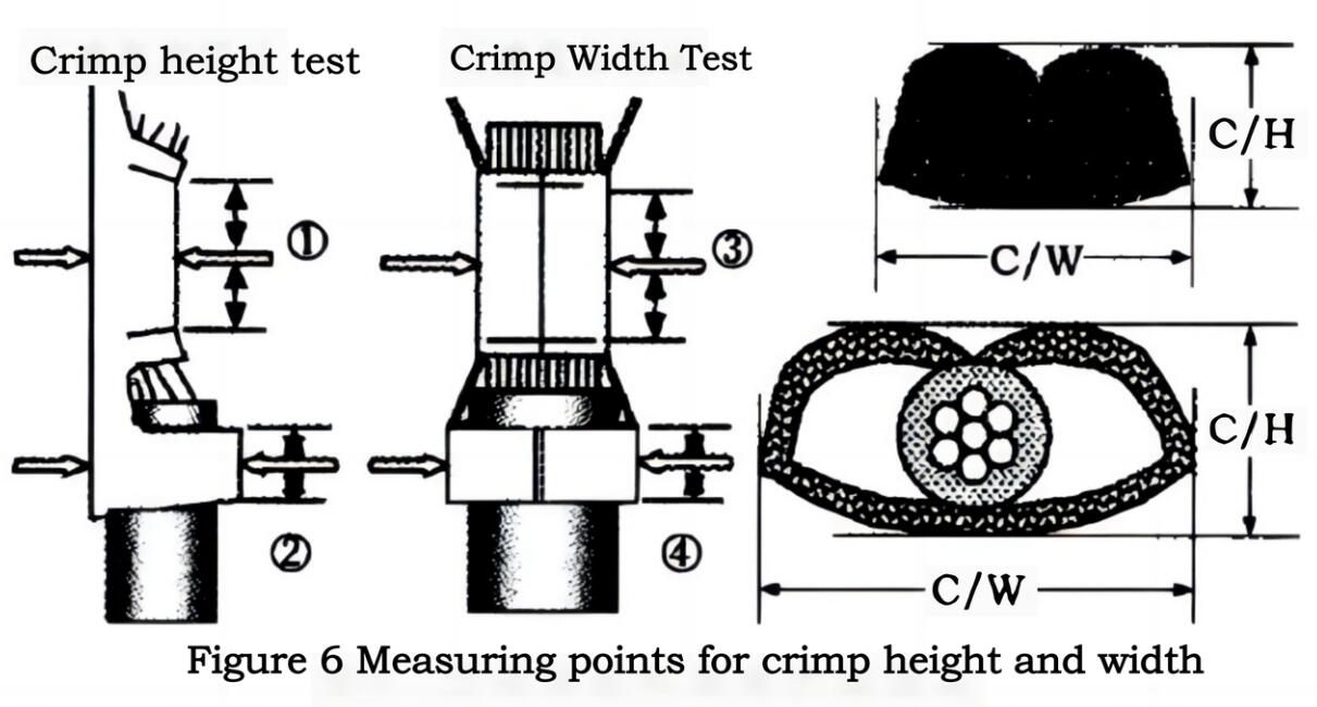
3.61. Measuring points for crimp height and width
The measurement area for crimp height and width is generally selected in the middle of the core and insulation crimp area, as shown in Figure 6.
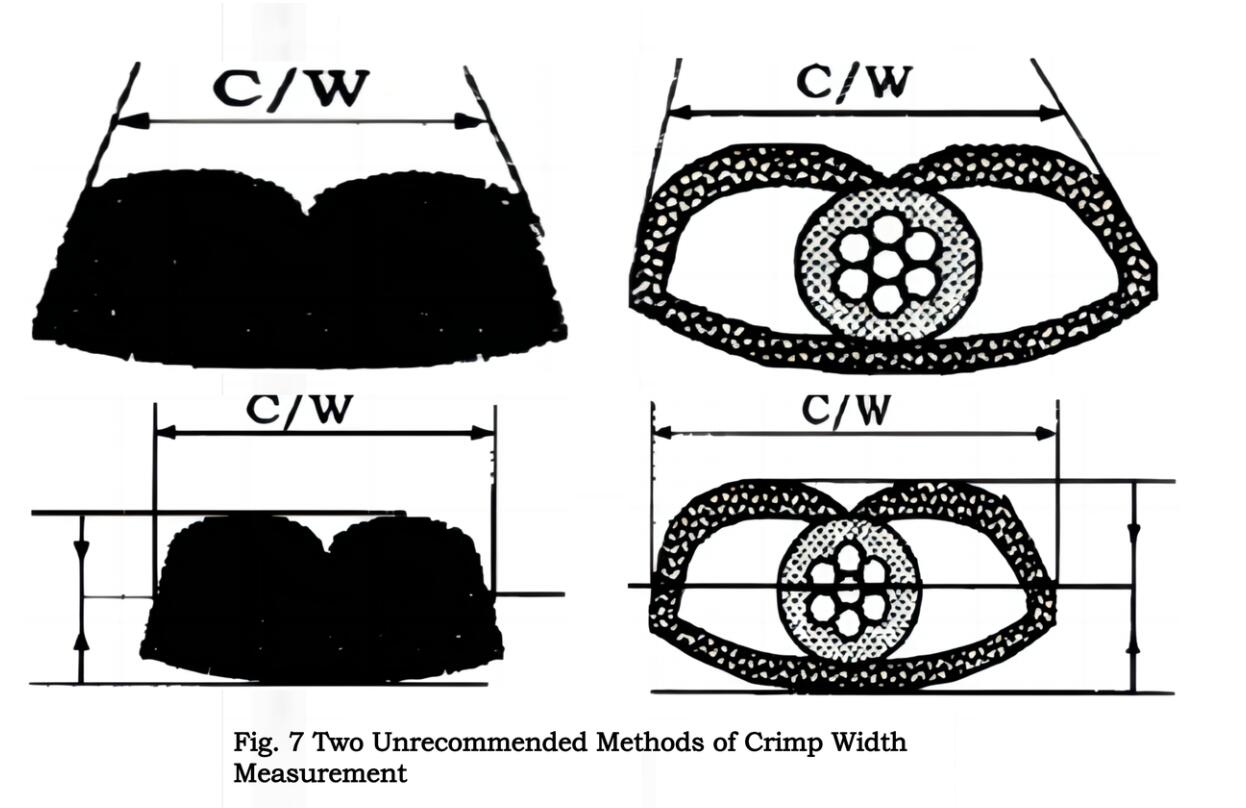
Measurement of crimp width in the current there are objections, some people believe that crimp width measurement can not measure the total width, should be measured at the crimp between the two arcs and the tangent point of the inclined surface of the distance, as shown in Figure 7, but this measurement method is less than ideal, the measurement is difficult, it is difficult to find the right measurement point.
Others believe that the measurement point of the crimp width in the midpoint of the two sides of the surface, as shown in Figure 7, this measurement method is also not ideal, the two sides of the surface is composed of curved surfaces and sloped surfaces, it is difficult to find the midpoint of the measurement is difficult to measure the measured value is not stable, the measurement error is too large, these two measurement methods are not recommended.
3.62. Use of measuring instruments
Measurement of crimp height using a micrometer with a cone at one end, and measurement of crimp width using a micrometer with flat surfaces at both ends, as shown in Figure 8. Measurement of crimp height measurement without ribbed parts, can not use both ends of the plane of the micrometer to measure the crimp height, because the measured value is not the true value.
(Continued)
Lead Tech is a professional company who has been dealing with automotive connectors supplying for over 10 years,
who happens to be a specialist mainly help you solve your supplying urgencies.